
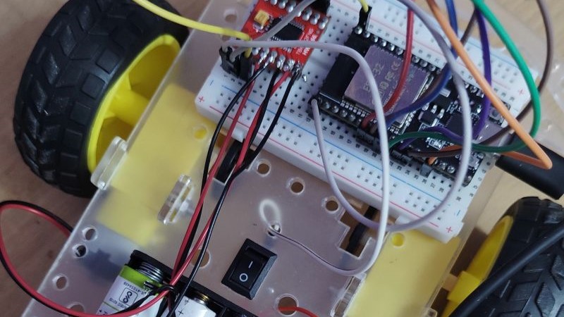
A 2WD robot car controlled by an ESP32 over Wi-Fi using a WebSocket-based web interface.
This project is built as a hands-on embedded systems learning project using C++, ESP32, FreeRTOS, Wi-Fi, WebSocket, GPIO, and the TB6612FNG motor driver.
Overview
The car uses an ESP32 as the main controller.
The ESP32 creates its own Wi-Fi network and hosts a web page. A phone or computer connects to this network and opens the control interface.
The control commands are sent from the browser to the ESP32 using WebSocket.
The ESP32 then sends motor-control signals to the TB6612FNG motor driver.
                  PHONE / PC
                       |
                       | Wi-Fi
                       |
                       v
                +--------------+
                |    ESP32     |
                |              |
                | WebSocket    |
                +------+-------+
                       |
                  GPIO signals
                       |
                       v
                +--------------+
                |  TB6612FNG   |
                | Motor Driver |
                +------+-------+
                       |
                +------+------+
                |             |
                v             v
           LEFT MOTOR    RIGHT MOTOR
Current Status
The current version is working.
Implemented:
- 2WD robot chassis
- Two DC geared motors
- TB6612FNG motor driver
- ESP32 NodeMCU-32S
- ESP32 Wi-Fi Access Point
- HTTP web server
- WebSocket communication
- Browser-based control interface
- Forward movement
- Backward movement
- Left turn
- Right turn
- Stop
- WebSocket disconnect safety stop
- FreeRTOS task separation
- Core 0 web task
- Core 1 car-control task
- FreeRTOS command queue
The HC-SR04 ultrasonic sensor is not used in the current version.
Hardware
Components
| Component | Quantity | Purpose | Approx. Cost |
|---|---|---|---|
| ESP32 NodeMCU-32S | 1 | Main controller | ₹399 |
| 2WD Robot Car Kit | 1 | Chassis, motors, wheels, battery holder | ₹279 |
| TB6612FNG Dual DC Motor Driver | 1 | Motor control | ₹133 |
| AA Batteries | 4 | Motor power | Existing |
| Jumper Wires | As required | Connections | Existing |
| USB Cable | 1 | ESP32 power/programming | Existing |
Approximate cost of the main purchased components:
ESP32          ₹399
2WD Kit        ₹279
TB6612FNG      ₹133
--------------------
Total          ₹811
Prices may change.
Purchase Links
ESP32 NodeMCU-32S
https://robocraze.com/products/nodemcu-32-wifi-bluetooth-esp32-development-board30-pin
2WD Robot Car Kit
https://robocraze.com/products/2wd-two-wheel-drive-diy-kit-a-smart-robot-car-with-chassis
TB6612FNG Dual DC Motor Driver
https://robocraze.com/products/tb6612fng-dual-dc-motor-driver
Hardware Architecture
The ESP32 does not directly drive the motors.
The ESP32 GPIO pins provide low-power control signals to the TB6612FNG.
The TB6612FNG handles the motor-side electrical power.
ESP32 GPIO
    |
    | Direction / Enable
    v
TB6612FNG
    |
    | Motor power
    v
DC Motors
The TB6612FNG contains two motor-control channels:
              TB6612FNG

        +-------------------+
        |                   |
        |    Channel A      |---- Left Motor
        |                   |
        |    Channel B      |---- Right Motor
        |                   |
        +-------------------+
Wiring
ESP32 to TB6612FNG
| ESP32 | TB6612FNG | Purpose |
|---|---|---|
| GPIO 25 | PWMA | Left motor speed/enable |
| GPIO 26 | AIN1 | Left motor direction |
| GPIO 27 | AIN2 | Left motor direction |
| GPIO 14 | PWMB | Right motor speed/enable |
| GPIO 32 | BIN1 | Right motor direction |
| GPIO 33 | BIN2 | Right motor direction |
| GPIO 13 | STBY | Motor driver enable |
| 3.3V | VCC | Logic supply |
| GND | GND | Common ground |
Wiring diagram
ESP32                         TB6612FNG
------------------------------------------------

GPIO 25  ------------------> PWMA
GPIO 26  ------------------> AIN1
GPIO 27  ------------------> AIN2

GPIO 14  ------------------> PWMB
GPIO 32  ------------------> BIN1
GPIO 33  ------------------> BIN2

GPIO 13  ------------------> STBY

3.3V     ------------------> VCC
GND      ------------------> GND
Motor Connections
The left motor is connected to Channel A.
TB6612FNG

AO1 -------- Left Motor
AO2 -------- Left Motor
The right motor is connected to Channel B.
TB6612FNG

BO1 -------- Right Motor
BO2 -------- Right Motor
A DC motor changes its rotation direction when the polarity across its terminals is reversed.
During testing, the right motor rotated in the opposite direction.
The two right-motor wires were swapped to correct the direction.
Power
During development, the ESP32 is powered through USB from the laptop.
The motors receive power from the battery holder through the TB6612FNG.
                 LAPTOP
                    |
                   USB
                    |
                    v
                +-------+
                | ESP32 |
                +---+---+
                    |
                 GPIOs
                    |
                    v
              +-----------+
              | TB6612FNG |
              +-----+-----+
                    |
              +-----+-----+
              |           |
              v           v
         LEFT MOTOR   RIGHT MOTOR
The motor battery is connected to the motor driver's motor-voltage input.
Battery +
    |
  Switch
    |
    v
TB6612 VM

Battery -
    |
    v
TB6612 GND
The ESP32 and TB6612FNG share a common ground.
ESP32 GND
    |
    +---------- TB6612FNG GND
                     |
                     +---------- Battery -
Important
The ESP32 is currently powered through USB during development.
The motor battery supply is separate.
Do not connect a battery directly to the ESP32 5V pin unless its voltage is known to be within the board's acceptable input range.
Software
Development Environment
Operating System : Windows 10
IDE              : VS Code
Build System     : PlatformIO
Framework        : Arduino
Language         : C++
Board            : NodeMCU-32S
Project Structure
The code is separated into three main parts.
ESP32_TB6612FNG_Web_controlled_Car/
│
├── platformio.ini
├── README.md
│
└── src/
    │
    ├── main.cpp
    │
    ├── webpage.cpp
    ├── webpage.h
    │
    ├── car.cpp
    └── car.h
main.cpp
Responsible for:
- Starting the application
- Creating the FreeRTOS command queue
- Creating the web task
- Creating the car task
- Assigning tasks to CPU cores
webpage.cpp
Responsible for:
- Wi-Fi Access Point
- HTTP server
- WebSocket server
- HTML
- CSS
- JavaScript
- Receiving commands from the browser
- Sending commands to the FreeRTOS queue
car.cpp
Responsible for:
- TB6612FNG initialization
- Motor GPIO configuration
- Forward movement
- Backward movement
- Left turn
- Right turn
- Stop
Wi-Fi
The ESP32 runs in Access Point mode.
It creates its own Wi-Fi network.
SSID:     ESP32-CAR
Password: esp32car
IP:       192.168.4.1
The phone connects directly to the ESP32.
Phone
  |
  | Wi-Fi
  v
ESP32-CAR
Internet access is not required.
Web Interface
The ESP32 hosts a simple control webpage.
The interface is arranged with movement controls on the sides and the connection status and STOP button in the center.
+-------------------------------------------+
|                 ESP32 CAR                 |
|                                           |
|                 Connected                 |
|                                           |
|     +-----+                 +-----+       |
|     |  ▲  |                 |  ◀  |       |
|     +-----+                 +-----+       |
|                                           |
|     +-----+       +------+  +-----+       |
|     |  ▼  |       | STOP |  |  ▶  |       |
|     +-----+       +------+  +-----+       |
|                                           |
+-------------------------------------------+
Left side:
▲ UP
▼ DOWN
Right side:
◀ LEFT
▶ RIGHT
Center:
Connection Status
       |
      STOP
WebSocket
The browser communicates with the ESP32 using WebSocket.
The WebSocket server runs on port 81.
Phone Browser
      |
      | WebSocket
      v
ws://192.168.4.1:81/
Commands are sent as text.
| Browser Command | Internal Command | Action |
|---|---|---|
UP |
CMD_FORWARD |
Forward |
DOWN |
CMD_BACKWARD |
Backward |
LEFT |
CMD_LEFT |
Turn left |
RIGHT |
CMD_RIGHT |
Turn right |
STOP |
CMD_STOP |
Stop |
Example:
Phone
  |
  | "UP"
  v
WebSocket
  |
  v
ESP32
  |
  | CMD_FORWARD
  v
Car Task
  |
  v
TB6612FNG
  |
  v
Motors
Button Behaviour
The movement buttons use press-and-release control.
For example:
Finger touches UP
        |
        v
      "UP"
        |
        v
   Car moves forward
        |
        |
Finger releases UP
        |
        v
     "STOP"
        |
        v
     Car stops
This prevents the car from continuing to move after the user releases the movement button.
Dual-Core Architecture
The ESP32 has two CPU cores.
The application separates the web and car-control tasks.
                 ESP32
        +----------------------+
        |                      |
        |      CPU CORES       |
        |                      |
        |  Core 0    Core 1    |
        |    |         |       |
        +----|---------|-------+
             |         |
             v         v
          WEB TASK   CAR TASK
Current task assignment:
Core 0
 |
 +-- Web Task
     |
     +-- HTTP Server
     +-- WebSocket


Core 1
 |
 +-- Car Task
     |
     +-- Motor Control
     +-- TB6612FNG
The networking code does not directly control the motor GPIO pins.
FreeRTOS Command Queue
The web task and car task communicate through a FreeRTOS queue.
                    CORE 0
                      |
                  WebSocket
                      |
                      v
                  "UP"
                      |
                      v
             +----------------+
             | FreeRTOS Queue |
             +-------+--------+
                     |
                     v
                    CORE 1
                     |
                  Car Task
                     |
                     v
               carForward()
                     |
                     v
                 TB6612FNG
                     |
                +----+----+
                |         |
                v         v
              Motor     Motor
The queue separates network handling from hardware control.
This prevents the WebSocket callback from directly manipulating the motor hardware.
Motor Control
The TB6612FNG uses two direction pins for each motor.
For the left motor:
AIN1 = HIGH
AIN2 = LOW
moves in one direction.
AIN1 = LOW
AIN2 = HIGH
moves in the opposite direction.
The right motor works similarly:
BIN1 = HIGH
BIN2 = LOW
and:
BIN1 = LOW
BIN2 = HIGH
The STBY pin must be HIGH for the motor driver to operate.
STBY = HIGH
For the current initial motor test, PWMA and PWMB are held HIGH.
PlatformIO Configuration
platformio.ini:
[env:nodemcu-32s]

platform = espressif32

board = nodemcu-32s

framework = arduino

monitor_speed = 115200

lib_deps =
    links2004/WebSockets
Running the Project
Connect the ESP32 to the computer using USB.
Build and upload the project using PlatformIO.
Open the Serial Monitor:
115200 baud
The ESP32 should display:
================================
     ESP32 WEB CONTROL CAR
================================
[MAIN] Command queue created
[WEB] Running on core 0
[CAR] Running on core 1
[CAR] Motor controller initialized
[WEB] Starting Wi-Fi AP...
[WEB] SSID: ESP32-CAR
[WEB] IP: 192.168.4.1
[WEB] HTTP server started
[WEB] WebSocket started
Connect the phone to:
ESP32-CAR
Password:
esp32car
Then open:
http://192.168.4.1
The web interface should appear.
Testing
For the first motor test, keep the wheels lifted from the ground.
Test each control individually:
UP
DOWN
LEFT
RIGHT
STOP
The Serial Monitor should show messages similar to:
[WS] Client connected

[WS] Command: UP
[CAR] FORWARD

[WS] Command: STOP
[CAR] STOP

[WS] Command: LEFT
[CAR] LEFT

[WS] Command: STOP
[CAR] STOP
After verifying that the controls work correctly, the car can be placed on the floor for controlled testing.
Safety
Always test the car with the wheels lifted from the ground after making wiring or software changes.
Before powering the motor driver:
- Check the motor wiring.
- Check the common GND.
- Check the TB6612FNG connections.
- Make sure the car cannot drive into anything.
- Keep the emergency STOP control accessible.
The WebSocket disconnect handler also sends a STOP command to the car-control task.
WebSocket connection lost
          |
          v
      CMD_STOP
          |
          v
      Car Task
          |
          v
    Motors stopped
Learning Concepts
This project combines several embedded-system concepts.
ESP32
The ESP32 acts as the main microcontroller.
ESP32
 |
 +-- Wi-Fi
 +-- GPIO
 +-- FreeRTOS
 +-- WebSocket
 +-- C++
TB6612FNG
The TB6612FNG acts as the motor driver.
ESP32
  |
  | Logic signals
  v
TB6612FNG
  |
  | Motor power
  v
DC Motors
GPIO
GPIO pins are used to send digital control signals from the ESP32 to the TB6612FNG.
Wi-Fi
The ESP32 creates its own wireless network.
WebSocket
WebSocket provides a persistent connection between the browser and ESP32.
FreeRTOS
FreeRTOS provides the task and queue system used to separate web handling from car control.
C++
The firmware is written using C++ with the Arduino framework.
Complete System
The complete system can be represented as:
                         PHONE
                           |
                           |
                         Wi-Fi
                           |
                           v
                  +----------------+
                  |     ESP32      |
                  |                |
                  |    CORE 0      |
                  |                |
                  | HTTP/WebSocket |
                  +-------+--------+
                          |
                     Command Queue
                          |
                          v
                  +----------------+
                  |     CORE 1     |
                  |                |
                  |    Car Task    |
                  +-------+--------+
                          |
                       GPIO
                          |
                          v
                  +----------------+
                  |   TB6612FNG    |
                  | Motor Driver   |
                  +-------+--------+
                          |
                   +------+------+
                   |             |
                   v             v
              LEFT MOTOR    RIGHT MOTOR
Current GPIO Map
                ESP32

GPIO 25  ----------> PWMA
GPIO 26  ----------> AIN1
GPIO 27  ----------> AIN2

GPIO 14  ----------> PWMB
GPIO 32  ----------> BIN1
GPIO 33  ----------> BIN2

GPIO 13  ----------> STBY

3.3V     ----------> VCC
GND      ----------> GND
Repository Structure
ESP32_TB6612FNG_Web_controlled_Car/
│
├── platformio.ini
├── README.md
│
└── src/
    │
    ├── main.cpp
    │
    ├── webpage.cpp
    ├── webpage.h
    │
    ├── car.cpp
    └── car.h
Summary
The current system consists of:
ESP32
   |
   | Wi-Fi
   v
Web Browser
   |
   | WebSocket
   v
ESP32
   |
   | FreeRTOS Queue
   v
Car Task
   |
   | GPIO
   v
TB6612FNG
   |
   +------ Left Motor
   |
   +------ Right Motor
The ESP32 successfully receives movement commands through a WebSocket connection and passes those commands to the car-control task, which controls the TB6612FNG motor driver.
Project status: Working